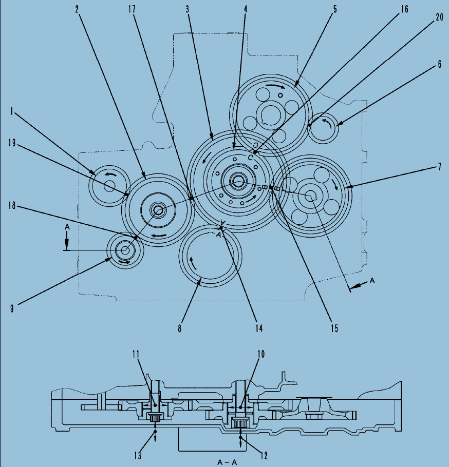

Timing gear docking diagram

Teaching Method of Adjusting Valve Clearance
| Mark | Part Number | Part name |
| A | Market purchase | Feeler gauge |
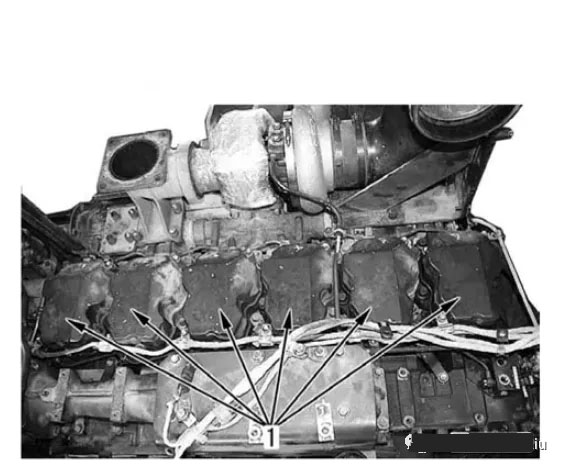
I. Unload six-cylinder heads

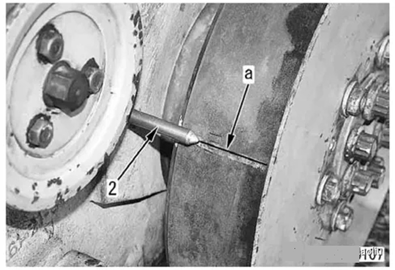
II. Turn the crankshaft forward and set the "1.6TOP" mark of the shock absorber
(a) Align with pointer ⑵ and adjust No. 1 cylinder to compression top dead center.
★ Rotate the crankshaft at the hexagonal part at the end of the water pump to drive the shaft.
★ When the No. 1 cylinder is at the top dead center of compression, you can manually move the rocker arm of the No. 1 cylinder to the gap of the air valve. If it cannot be moved, the crankshaft can be rotated for more than one revolution.

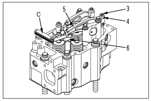
III. Loosen the lock nut ⑷ when adjusting the screw (3).
★ After the No. 1 cylinder is set at the top dead center of compression, adjust the valve clearance of the No. 1 cylinder.
IIII. Insert the feeler gauge C into the gap between the rocker arm ⑸ and the crosshead ⑹, and use the adjusting screw ⑶ to adjust the air valve gap.
★ Insert the feeler gauge and set the adjusting screw to the point where you can move the feeler gauge slightly.
★ Air valve clearance, intake valve: 0.35mm, exhaust valve: 0.57mm
IIIII. When fixing the adjusting screw (3), tighten the locknut (4).
Nut: 45.1-51.0Nm {4.6-5.2kgm}.
★After tightening the lock nut, check the air valve gap again.

IIIIII. After the No. 1 cylinder is adjusted, rotate the crankshaft forward 120°, and according to the point
Adjust the clearance of each cylinder in the fire sequence.
★ Ignition sequence: 1-5-3-6-2-4