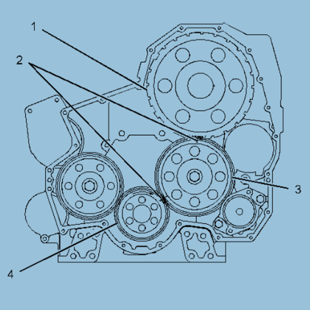


Front gear assembly
(1) Camshaft gear and timing reference ring
(2) Timing mark
(3) Idler gear
(4) Crankshaft gear
The basis for correct fuel injection timing and valve train operation depends on the positioning of the timing reference ring and the front gear assembly. The timing reference ring is located at the end of the camshaft. The timing reference ring is used to measure the crankshaft speed. During the installation of the front gear, the timing mark (2) on the idler gear (3) must be aligned with the timing mark (4) on the crankshaft gear and the timing mark (1) on the camshaft gear.
Engine valve clearance check/adjust
Note: The valve clearance is measured between the rocker arm and the valve bridge of the intake valve. Measure the valve clearance between the rocker arm and the valve stem of the exhaust valve. All clearance measurements and adjustments must be carried out when the engine is stopped. The valve must be completely closed.
Intake Valve | Exhaust Valve | |
| Valve Clearance Check | 0.38±0.08mm(0.0150±0.0031 in) | 0.64±0.08mm(0.0252±0.0031 in) |
| Endpoint of Compression Stroke | 1-2-4 | 1-3-5 |
| Exhaust Stroke End Point | 3-5-6 | 2-4-6 |
| Ignition Sequence | 1-5-3-6-2-4 | |
(1) 360° from the top dead center of the compression stroke
(2) The No. 1 cylinder is at the front end of the engine.
If the measured value of the valve clearance is within the acceptable range, no adjustment is necessary. Check the valve clearance when the engine is stopped. The range is listed in Table 1.
If the measured value is not within this range, it is necessary to make adjustments. Please refer to Test and Adjustment, "Valve Clearance and Valve Bridge Adjustment.

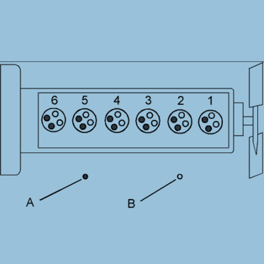
Cylinder and valve position
(A) Exhaust valve
(B) Inlet valve
Valve clearance and valve bridge adjustment
| Valve clearance | |
| Valve | Gauge size |
| Intake | 0.38±0.08mm(0.0150±0.0031 in) |
| Exhaust | 0.64±0.08mm(0.0252±0.0031 in) |
Check the valve clearance when the engine is stopped. Use the following procedure to adjust the valve.Place the No. 1 piston at the top dead center 1.position of the compression stroke.
| Endpoint of Compression Stroke | Intake Valve | Exhaust Valve |
| Valve Clearance | 0.38±0.08mm(0.0150±0.0031 in) | 0.64±0.08mm(0.0252±0.0031 in) |
| Cylinder | 1-2-4 | 1-3-5 |
2. Adjust the valve clearance according to Table 3.
a. Use a soft hammer to gently tap the rocker arm on the top of the adjustment screw. This ensures that the tappet roller is seated on the base circle of the camshaft.
b. Loosen the adjustment lock nut.
c. Place an appropriate feeler gauge between the rocker arm and the valve bridge. Then, turn the adjustment screw clockwise. Slide the feeler gauge between the rocker arm and the valve bridge. Continue to turn the adjusting screw until you feel a slight drag on the feeler gauge. Remove the feeler gauge.
d. Tighten the adjusting lock nut to a torque of 30 ± 7 N·m (22 ± 5 lb-ft). Tighten the adjustment lock
Do not allow the adjusting screw to turn when tightening the nut. Recheck the valve clearance after tightening the adjusting lock nut.
3. Remove the timing bolt and turn the flywheel 360 degrees in the direction of engine rotation. This will place the No. 6 pistons at the top dead center (TC) position at the top dead center position of the compression stroke. Install the timing bolt on the flywheel.
| Exhaust Stroke End Point | Intake Valve | Exhaust Valve |
| Valve Clearance | 0.38±0.08mm(0.0150±0.0031 in) | 0.64±0.08mm(0.0252±0.0031 in) |
| Cylinder | 3-5-6 | 2-4-6 |
4. Adjust the valve clearance according to Table 4.
a. Use a soft hammer to gently tap the rocker arm on the top of the adjustment screw. This ensures that the tappet roller is seated on the base circle of the camshaft.
b. Loosen the adjustment lock nut.
c. Place an appropriate feeler gauge between the rocker arm and the valve bridge. Then, turn the adjustment screw clockwise. Slide the feeler gauge between the rocker arm and the valve bridge. Continue to turn the adjusting screw until you feel a slight drag on the feeler gauge. Remove the feeler gauge.
d. Tighten the adjusting lock nut to a torque of 30 ± 7 N·m (22 ± 5 lb ft). Tighten the adjustment lock
Do not allow the adjusting screw to turn when tightening the nut. Recheck the valve clearance after tightening the adjusting lock nut.
5. After all valve clearance adjustments are completed, remove the timing bolt from the flywheel. Put back the timing cover