

The drive pump and idler pump have the same regulator construction and operation. The pump regulator is located on the top of the main pump housing. The following is a description of the drive pump regulator.
The main pump regulator is controlled in the following way.
Powershift system-The pump regulator is controlled by an electronic control system. The machine ECM continuously monitors engine speed and engine load. The machine ECM sends an electrical signal to the power shift pressure proportional pressure reducing valve. The proportional pressure reducing valve assists in controlling the pump output flow by changing the hydraulic signal pressure (power shift pressure) transmitted to the pump regulator.
Mutual inductance control-The pump regulator is controlled by the mutual inductance control. In order to maintain the supply of engine power to the pump at a constant rate, the pump regulator receives the average output pressure of the drive pump and the idler pump through a mutual inductance control device. This operation is called stable power control.
Reverse Flow Control-When the joystick and/or travel joystick/pedal is in the neutral position, or when the joystick and/or travel joystick/pedal portion is moved from the neutral position, the pump regulator receives Reverse flow control pressure. At this time, the main pump is controlled by the reverse flow control pressure.
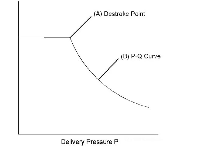
Figure 1
P-Q characteristic curve
(A) Pressure/flow point (decrease stroke point)
(B) P-Q characteristic curve
The output characteristics of each pump depend on the following pressures.
Pump delivery pressure (PD)
Mutual inductance control pressure (CF)
Powershift pressure (PS)
Reverse flow control pressure (PI)
The P-Q characteristic curve (B) shows the flow rate of each pump from the pressure/flow point (A). Each point on the P-Q characteristic curve represents the flow rate and pressure at which the pump output power is maintained at a steady rate
Pump regulators-standard designation
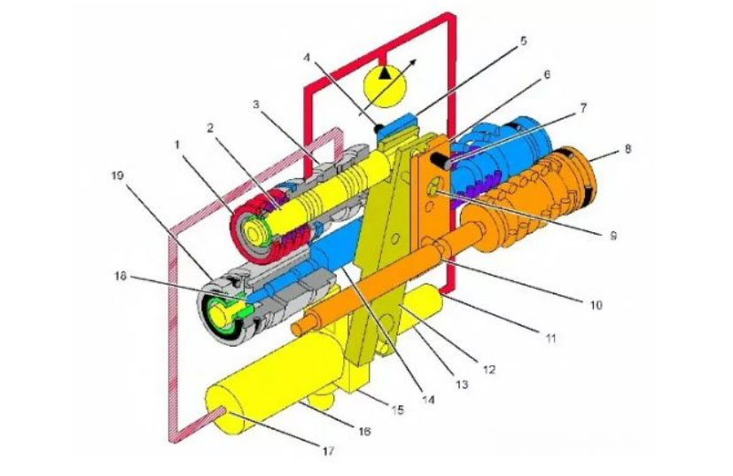
Figure 2
(1) Power control section
(2) Stable power control spool valve
(3) Power control sleeve
(4) Pivot pin
(5) Torque lever
(6) Reverse flow control joystick
(7) Pivot pin
(8) The reverse flow control part
(9) Pin (Feedback Joystick)
(10) The reverse flow control piston
(11) Maximum angle end of the actuator piston
(12) Feedback joystick
(13) The small end of actuator piston
(14) Torque control spool valve
(15) Actuator piston
(16) The big end of the actuator piston
(17) Minimum angle end of the actuator piston
(18) Torque control piston
(19) Torque control section
working principle:
Figure 2 shows three separate control sections of the pump control assembly. The three control sections are connected by a series of pins and links. The separate control parts work together and change the pump swash plate angle according to demand and hydraulic power requirements to adjust the pump flow.
The pump delivery pressure (PD) is directed to the small end of the actuator piston (13) to increase the stroke of the pump towards the maximum angle. The adjusted pressure signal is directed to the large end of the actuator piston (16) to reduce the stroke of the pump towards the smallest angle.
The power control section (1) guides part of the system pressure oil into and out of the large end of the large actuator piston (16). The lower end of the feedback lever (12) is connected to the actuator piston (15). The reaction lever (12) acts as a follower link to move the power control spool (2) when the actuator piston (15) moves.
The reverse flow control section (8) works in conjunction with the power control section (1) to reduce the swashplate stroke when all hydraulic controls are in the neutral position or during operation of the implement or driving function. The torque control section (19) works with the power control section (1) to regulate the pump flow when the hydraulic circuit is activated.
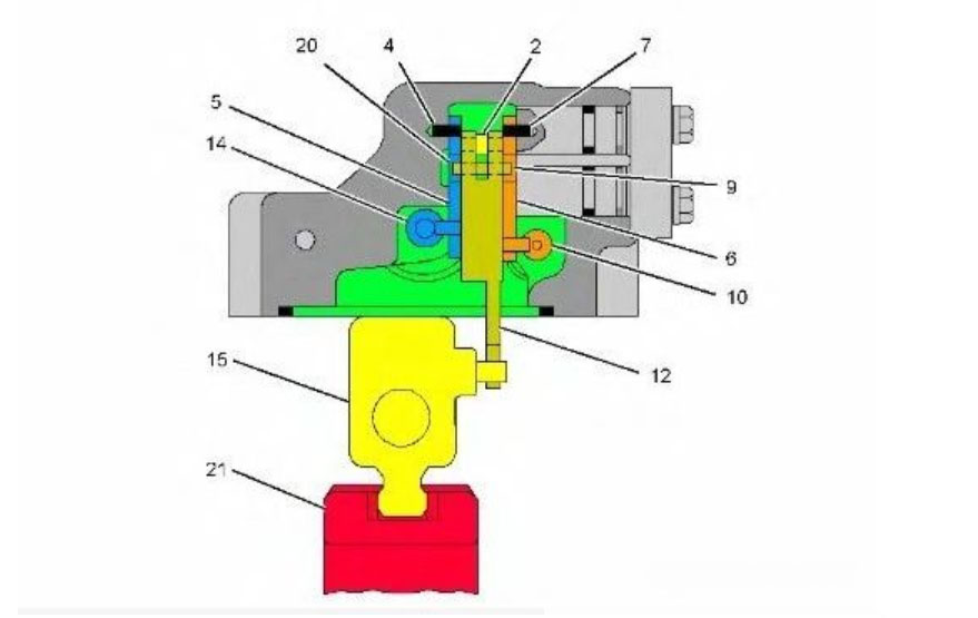
Figure 3
(2) Stable power control spool valve
(4) Pivot pin
(5) Torque lever
(6) Reverse flow control joystick
(7) Pivot pin
(9) Pin (Feedback Joystick)
(10) The reverse flow control piston
(12) Feedback joystick
(14) Torque control spool valve
(15) Actuator piston
(20) Big Hole
(21) Swashplate
Figure 3 shows an end section view of the pump control. The NFC piston (10) is connected to the lower end of the NFC joystick (6) by a pin. The upper end of the NFC joystick pivots on a pivot pin (7) in the housing. The torque control spool (14) is connected to the lower end of the torque lever (5) by a pin. The upper end of the torque lever is also pivoted on a pivot pin (4) in the housing. The upper end of the feedback lever (12) is connected to the power control slide valve (2) via a pin. The lower end of the feedback joystick is connected to the actuator piston (15). The pin of the feedback lever (9) fits tightly into the feedback lever (12). The pin of the feedback lever (9) extends into the large hole of the torque lever (5) and the NFC lever (6). The large hole allows separate control via the torque joystick (5) and NFC joystick (6). The movement of the actuator piston (15) causes the feedback lever (12) to pivot on the pin of the feedback lever (9) and moves the power control spool (2).
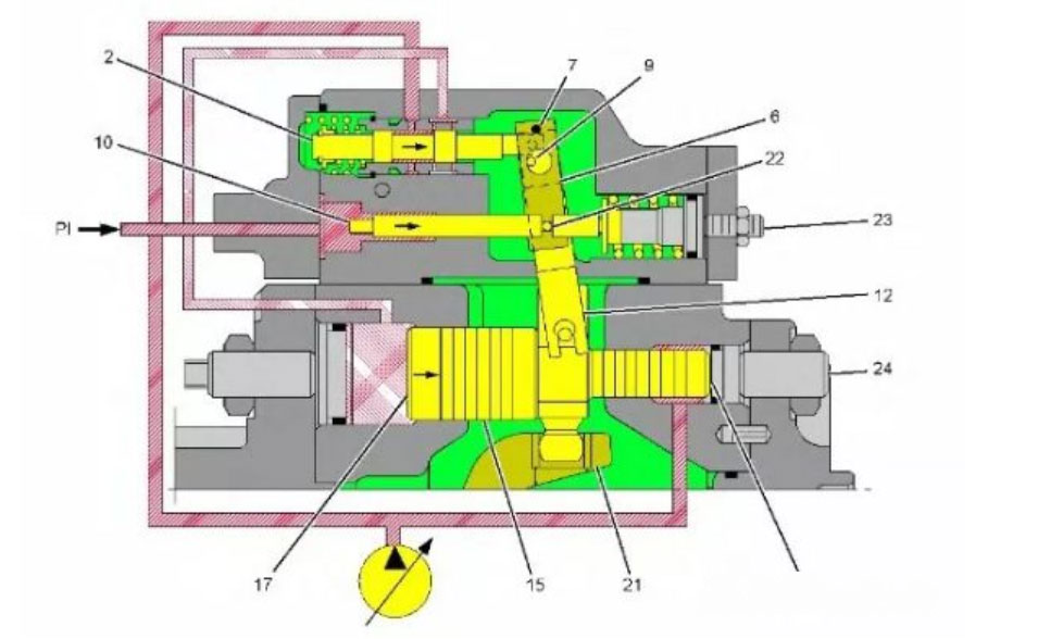
Figure 4
(2) Stable power control spool valve
(6) Reverse flow control joystick
(7) Pivot pin
(9) Pin (Feedback Joystick)
(10) The reverse flow control piston
(11) Maximum angle end of the actuator piston
(12) Feedback joystick
(15) Actuator piston
(17) Minimum angle end of the actuator piston
(21) Swashplate
(22) NFC joystick pin
(23) NFC adjustment screw
(24) Minimum angle limit
(PI) reverse flow control pressure
Figure 4 shows the reverse flow control section of the pump control assembly. When all hydraulic control valves are in neutral, high NFC pressure (system pressure) from the NFC orifice is directed to the left end of the NFC piston (10). The NFC pressure pushes the NFC piston (10) to the right against the spring force. In the standby state, the power control spool (2) directs the signal pressure as part of the system pressure to the minimum angled end of the actuator piston (17). The increased pressure causes the actuator piston (15) to move to the right against the minimum angle stop screw (24). The pump flow will remain constant until the NFC pressure from the control valve decreases. NFC adjusting screw (23) Changes the effect of NFC pressure on the NFC piston (10). Turning the screw in (clockwise) before the NFC piston (10) moves causes the NFC pressure to increase. When the hydraulic control valve is activated, this condition causes the pump to increase stroke more quickly (less modulation). Turning the NFC adjustment screw (23) outward (counterclockwise) will move the NFC piston (10) at a lower NFC pressure. When the hydraulic control valve is activated, this condition will make the pump slower and increase stroke (increase modulation).
Regulator operation (increased flow-start increasing stroke)
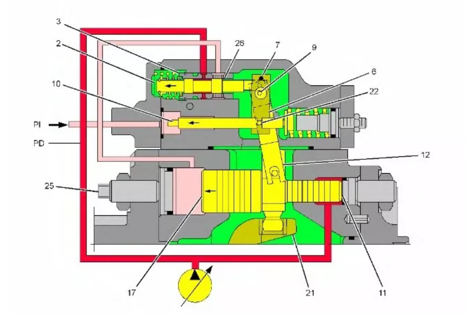
Figure 5
(2) Stable power control spool valve
(3) Power control sleeve
(6) Reverse flow control joystick
(7) Pivot pin
(9) Pin (Feedback Joystick)
(10) The reverse flow control piston
(11) Maximum angle end of the actuator piston
(12) Feedback joystick
(17) Minimum angle end of the actuator piston
(21) Swashplate
(22) NFC joystick pin
(25) Maximum angle limit
(26) Orifice
(PD) Pump output pressure
(PI) reverse flow control pressure
Figure 5 shows the pump control assembly at the beginning of an increased stroke caused by a decrease in NFC pressure (PI). The pivot pin (7) is fixed on the pump control housing. The NFC joystick (6) pivots around this point.
When the hydraulic control valve in the main control valve is switched, the NFC pressure decreases. Due to the reduced NFC pressure, the spring force moves the NFC piston (10) to the left. NFC piston (10) Move the lower end of the NFC joystick (6) to the left. As the lower end of the NFC joystick (6) moves to the left, the large hole passing through the joystick also moves to the left. When the large hole moves to the left, the spring force pulls the upper ends of the power control slide valve (2) and the feedback lever (12) to the left because the pin of the feedback lever (9) is allowed to move to the left. The smallest angled end of the actuator piston (17) communicates with the case drain through the right orifice (26) in the power control sleeve (3) and the right end of the power control spool (2). Pump delivery pressure (PD) Push the maximum angled end of the actuator piston (11) to the left to increase the stroke of the pump.
Regulator operation (constant flow)
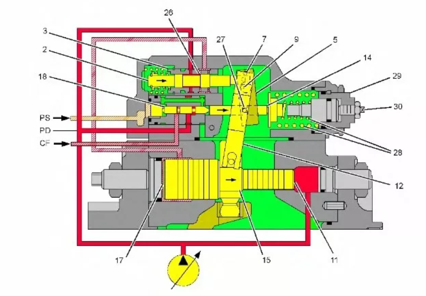
Figure 6
Pump regulator (constant flow)
(2) Stable power control spool valve
(3) Power control sleeve
(6) Reverse flow control joystick
(7) Pivot pin
(9) Pin (Feedback Joystick)
(10) The reverse flow control piston
(11) Maximum angle end of the actuator piston
(12) Feedback joystick
(15) Actuator piston
(17) Minimum angle end of the actuator piston
(21) Swashplate
(22) NFC joystick pin
(25) Maximum angle limit
(26) Orifice
(PI) reverse flow control pressure
When the actuator piston (15) moves, the lower end of the feedback lever (12) moves to the left. Turn the feedback joystick (12) clockwise, with the pin of the feedback joystick (9) as the pivot point. The upper end of the feedback lever (12) pulls the power control spool (2) to the right until the right shoulder on the power control spool (2) passes through the orifice (26) of the power control sleeve (3) A balance point is reached. Measure the flow into and out of the smallest angled end of the actuator piston (17) through the power control spool (2) and the power control sleeve (3). The angle of the swashplate (21) remains constant until the NFC pressure (PI) changes again.
Regulator operation (increased flow-fully increased stroke)
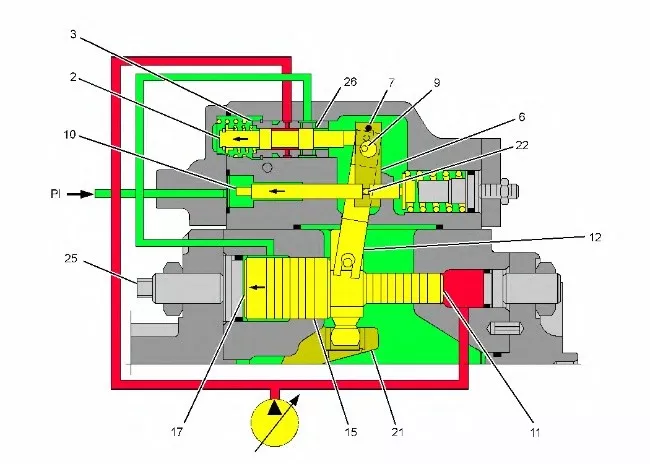
Figure 7
Pump regulator (increased flow-full stroke)
(2) Stable power control spool valve
(3) Power control sleeve
(6) Reverse flow control joystick
(7) Pivot pin
(9) Pin (Feedback Joystick)
(10) Reverse flow control piston
(11) Maximum angle end of the actuator piston
(12) Feedback joystick
(17) Minimum angle end of the actuator piston
(21) Swashplate
(22) NFC joystick pin
(25) Maximum angle limit
(26) Orifice
(PI) reverse flow control pressure
The reduction in NFC signal pressure (PI) determines the amount of pump stroke. If the NFC pressure is reduced to a minimum, the pump will increase the stroke until the actuator piston (15) contacts the maximum angle stop screw (25).
Note: A reduction in power shift pressure will cause an increase in pump flow in the same way as a decrease in system pressure, as both the power shift pressure and system pressure act on the torque control piston (18).
Regulator operation (reduced flow-start reducing stroke)
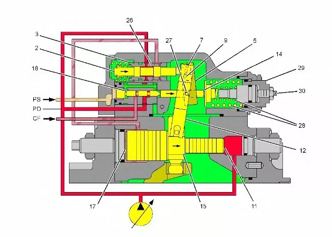
Figure 8
Pump regulator (reduced flow-start reducing stroke)
(2) Stable power control spool valve
(3) Power control sleeve
(5) Torque lever
(7) Pivot pin
(9) Pin (Feedback Joystick)
(11) Maximum angle end of the actuator piston
(12) Feedback joystick
(14) Torque control spool valve
(15) Actuator piston
(17) Minimum angle end of the actuator piston
(18) Torque control piston
(26) Orifice
(27) Torque lever pin
(28) Power control spring
(29) Adjustment screw (first stage of constant power control)
(30) Adjustment screw (second stage of constant power control)
(PD) Pump output pressure
(PS) Powershift pressure
(CF) Mutual inductance control pressure
Figure 8 shows the torque control piston (18) and the power control spool section of the pump control valve block, where the pump is in the increased stroke position when it begins to reduce the stroke due to the increased load on the system.
The pivot pin (7) is fixed on the pump control housing. The torque lever (5) pivots around a pivot pin (7).
Adjustment screw (29) for the first stage of constant power control to adjust the pressure or the point at which the pump starts to reduce stroke (large spring adjustment). The adjusting screw (30) for the second stage of constant power control adjusts the rate at which the pump reduces the stroke (small spring adjustment). The power shift pressure (PS) from the power shift PRV solenoid valve enters the pump control assembly and pushes the plug on the left end of the torque control piston (18). The pump delivery pressure (PD) from the drive pump enters the pump control valve group and reaches the right shoulder area on the torque control piston (18). The mutual induction signal pressure (CF) from the idler pump reaches the left shoulder area on the torque control piston (18). The combination of power shift pressure (PS), pump delivery pressure (PD) and mutual inductance control pressure (CF) will push the torque control piston (18) to the right against the force of the power control adjustment spring (28). The power control spool (2) directs the signal pressure to the smallest angled end of the actuator piston (17) to reduce the stroke of the hydraulic pump. When the pump delivery pressure (PD), mutual inductance control pressure (CF), and power shift pressure (PS) push the torque control piston (18) to the right: the torque control piston (18) moves to the right to compress the power control spring (28) ). The torque control piston (18) moves the lower end of the torque lever (5) to the right, with the fixing pin (7) at the upper end of the torque lever (5) as the pivot point. Torque lever (5) Pull the pin of the feedback lever (9) and the upper end of the feedback lever (12) to the right. The feedback lever (12) pulls the power control spool (2) to the right against the spring force. The pump delivery pressure (PD) is guided around the power control spool (2) through the central hole of the power control sleeve (3) and to the smallest angled end of the actuator piston (17). Increased pressure in the minimum angle piston (17) moves the actuator piston (15) to reduce the stroke of the pump.
Regulator operation (reduced flow-reduced stroke end)
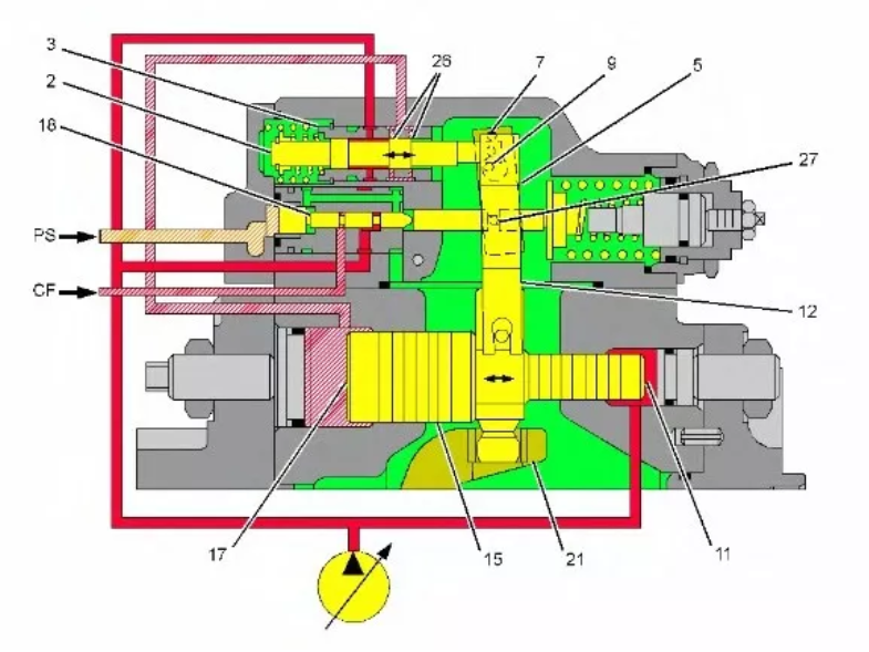
Figure 9
Pump regulator (reduced flow-reduced stroke end)
(2) Stable power control spool valve
(3) Power control sleeve
(5) Torque lever
(7) Pivot pin
(9) Pin (Feedback Joystick)
(11) Maximum angle end of the actuator piston
(12) Feedback joystick
(15) Actuator piston
(17) Minimum angle end of the actuator piston
(18) Torque control piston
(21) Swashplate
(26) Orifice
(27) Torque lever pin
(PS) Powershift pressure
(CF) Mutual inductance control pressure
Figure 9 shows the pump control assembly at the end of the reduced stroke due to the increased system load.
When the actuator piston (15) moves towards the minimum angle, the lower end of the feedback joystick (12) moves to the right and rotates the joystick counterclockwise, with the pin (9) of the feedback joystick as the pivot point. The movement of the feedback lever (12) moves the power control spool (2) to the left to meter the pump delivery pressure (PD) through two holes (26) at the minimum angle end of the actuator piston (17). Pump flow remains constant until one of the signal pressures changes. Since both the power shift pressure and the system pressure act on the torque control piston (18), an increase in power shift pressure (PS) will result in a decrease in the flow from the pump in the same way as described for an increase in system pressure.