
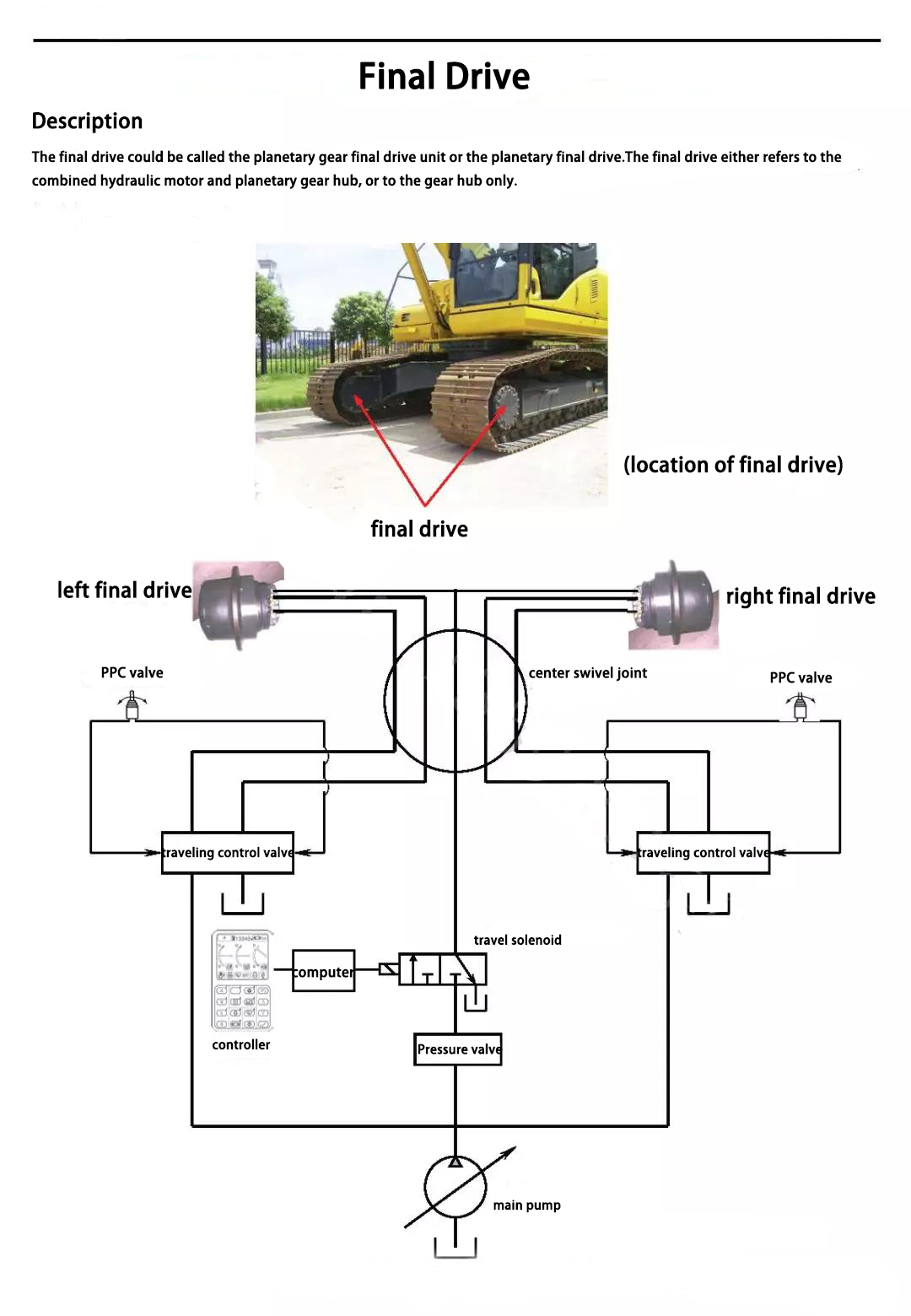
Appearance and structure
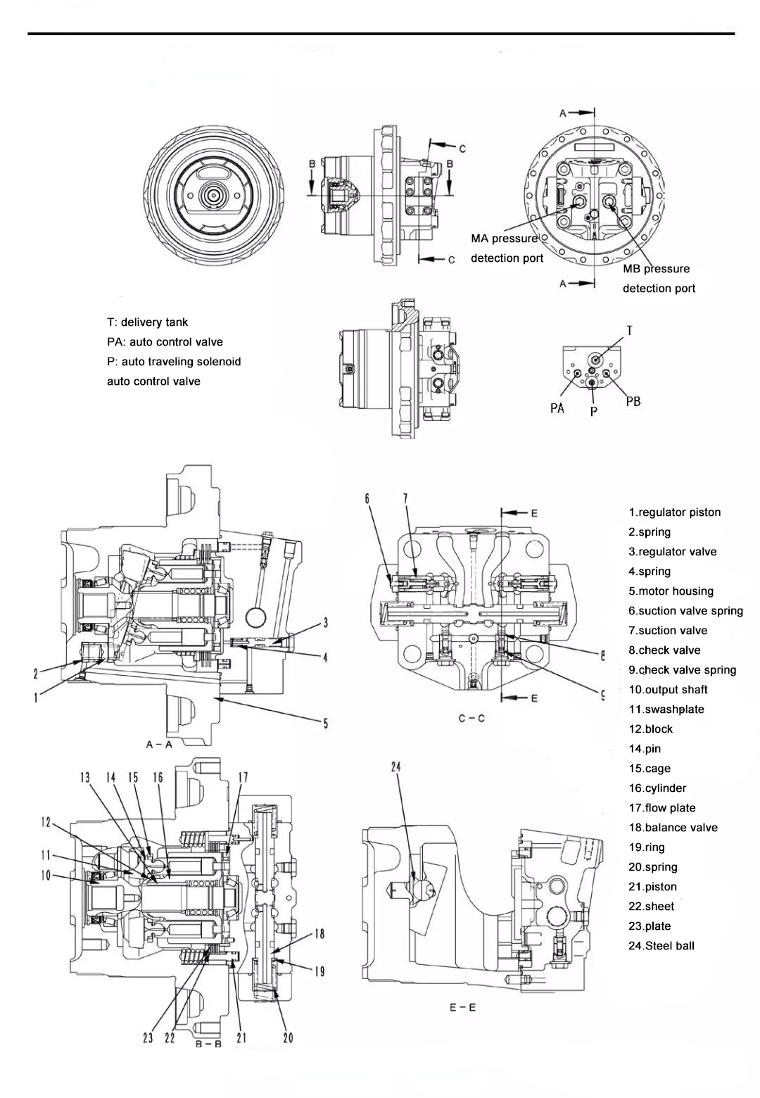
Component parts
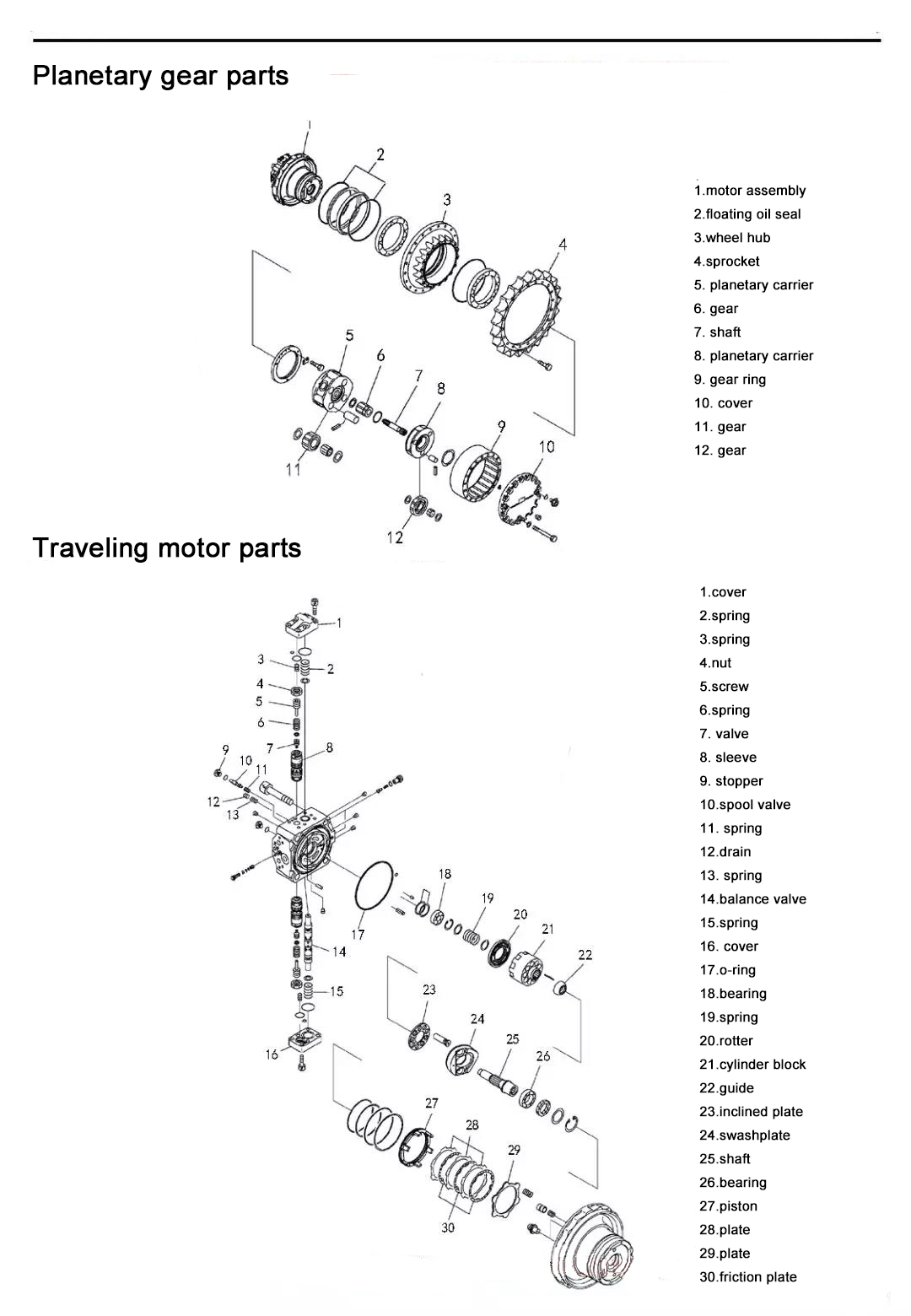
Note:
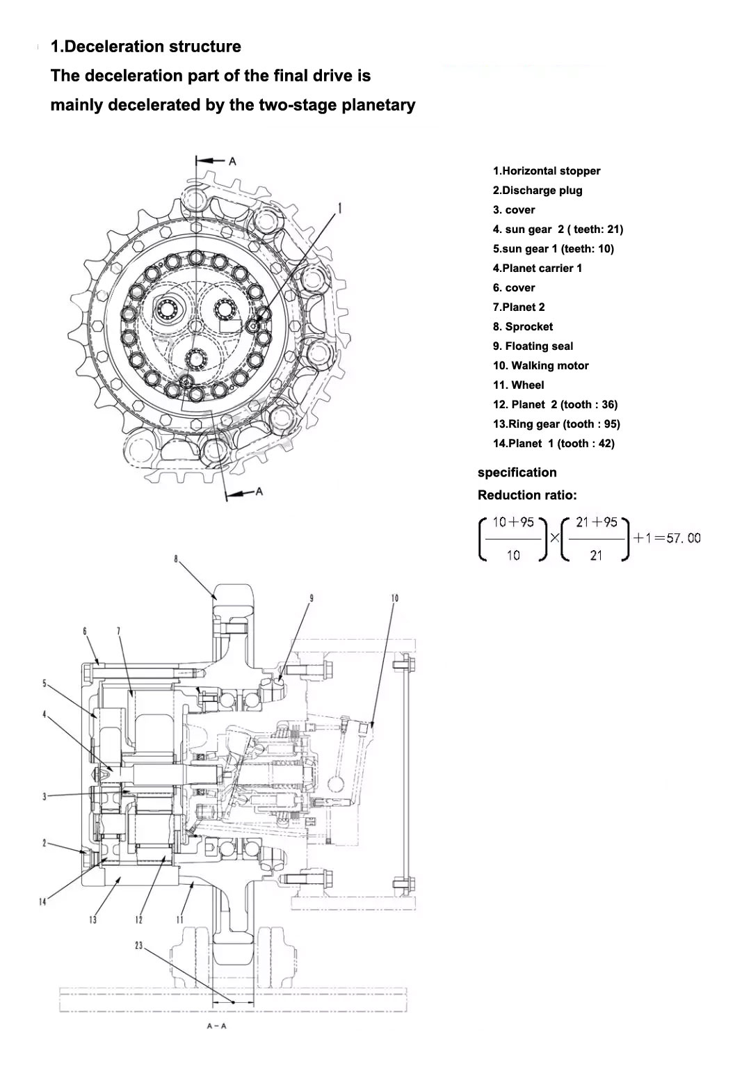
1. Pay attention to the installation of floating oil seals when disassembling the final drive
- When installing, wipe the two moving port faces of the floating oil seal clean;
- The 0 rings should be pressed into the installation groove, it should not slide out, and it is not allowed to smear engine oil. If the floating oil seal is not tight, it will leak oil;
2. After work every day, remove the dirt that is stuck on the outside of the final drive, so as to prevent the dirt from entering the open oil seal and causing oil leakage;
3. The engine oil must be replaced on time. If the oil is too dirty or deteriorated, the transmission gear will accelerate to wear or the performance of cold addition will be reduced, causing damage to the transmission performance.
Power transmission chain
Travel motor
↓
Output shaft
↓
Sun Gear 1
↓
Planetary Gear 1
↓
Planet carrier 1
↓
Sun Gear 2
↓
Planetary Gear 2
↓
Planet carrier 2
↓
Wheel hub
Motor working principle
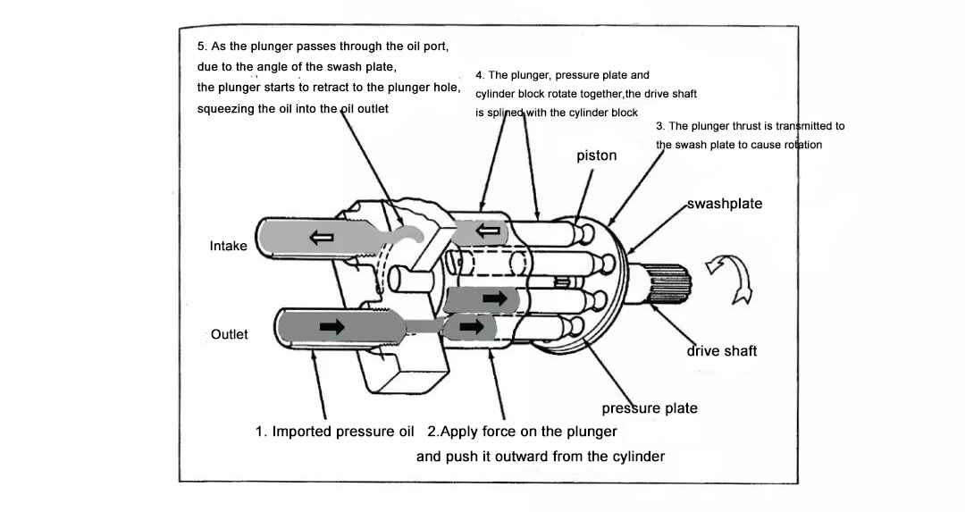
The motor is similar to the pump in structure. As a power output device of a hydraulic system, it does not push hydraulic oil like a pump, but is pushed by the high-pressure hydraulic oil and generates torque and continuous rotary motion.
The travel motor of the final drive is a straight shaft plunger motor. As shown in the figure below, the plunger motor generates torque by the pressure of the plunger portion acting on the cylinder. In the straight shaft structure, the motor drive shaft and the cylinder are centered on the same axis. The pressure at the end of the plunger causes a reaction force on the swashplate, driving the cylinder block and the motor shaft to rotate.
If the oil inlet and the oil outlet are swapped during use, the movement is opposite to the above, and the drive shaft rotates in the opposite direction.
Working Principle
2. Travel motor
1. Function
● Role of the hydraulic motor
- This hydraulic motor is a swashplate type axial piston motor, which converts the hydraulic pressure of the pressure oil transmitted from the main pump into a rotary motion.
● the role of the brake valve (the brake valve includes a safety suction valve, a balance valve)
- Controls the inertia force of the walking motor that must be rotated due to the inertia of the car body when the walking motor stops, and smoothly brakes it to stop.
● The role of the parking brake
- The parking brake plays a role of preventing the slippage and slippage caused by the excavator stopping on the inclined ground through the friction plate brake mechanism and is integrated with the hydraulic motor part.
2. Working process
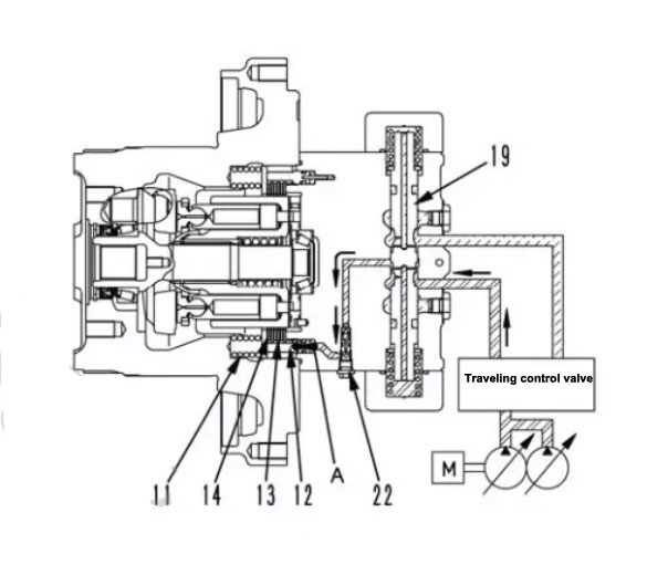
1) Release the brake
Operate the walking joystick
↓
The hydraulic oil from the control valve enters through the small hole in the balance valve (19).
Inlet balancing valve (19)
↓
Balance valve (19) moves up
↓
Pressure oil enters cavity A of the brake piston (12) in the direction of the arrow
↓
The force of the spring (11) on the plate (13) and the disc (14) is canceled
↓
Brake release
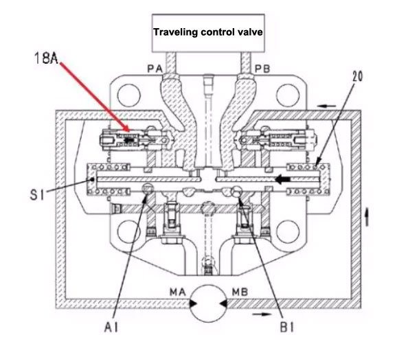
2) When walking
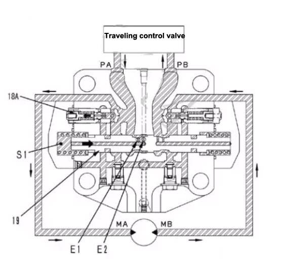
Pressure oil from the control valve is delivered to port PA
↓
The pressure oil flows through the orifices E1 and E2 in the spool valve (19) to the cavity S1
↓
Slide valve (19) is pushed to the right in the direction of the arrow
↓
At the same time, the pressure oil at the PA port pushes open the safety suction valve (18A)
↓
Flow into the MA port of the walking motor and flow out from the MB port, and drive the motor to rotate
↓
The pressure oil flowing from the MB port flows back to the PB port in the direction of the arrow.
3) When you stop walking
Walking joystick back to neutral
↓
Motor oil inlet PA is cut off
↓
Pressure drop in S1 cavity
↓
Balance valve returns to neutral position
↓
Outlet channel B1 is cut off
↓
The motor keeps inertial rotation, causing the pressure on the MB port to rise continuously
↓
The pressure at the MB port prevents the motor from continuing to rotate and generates a braking effect
↓
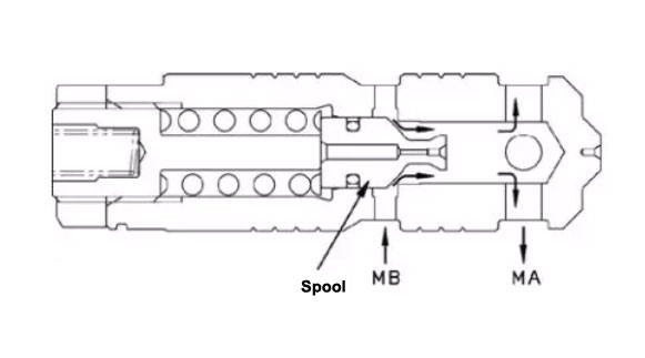
When the pressure at the MB port reaches a certain value, the high-pressure oil ejects the spool of the safety suction valve (18A) from the side.
↓
The high-pressure oil flows into the MA port of the walking motor through the safety suction valve (18A), preventing the generation of air pockets
When the balance valve returns to the neutral position
↓
Oil circuit from the control valve to cavity A is cut off
↓
The disc (13) and the disc (14) are pushed together by the spring (11) to generate a brake
4) Adjustment of motor speed
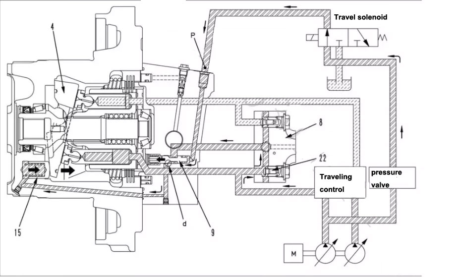
When the flow of the pump is constant, the rotation speed of the motor can be changed by changing the angle of the motor swashplate (4).
● On the monitoring panel, select the medium speed (Mi) or low speed (Lo)
↓
Travel speed solenoid is not energized
↓
The pilot oil from the self-relief valve cannot flow to the port face of the regulator valve (9).
↓
The angle of the swashplate (4) of the travel motor is at the maximum position
↓
Large walking motor capacity and low speed
● When walking high speed (Hi) is selected on the monitoring panel
↓
Travel speed solenoid is energized
↓
The pilot oil from the pressure reducing valve flows to the regulator valve (9) through the travel speed solenoid valve
↓
The spool of the regulator valve (9) is pushed to the left
↓
The main pressure oil from the control valve enters the regulator piston (15) at the bottom through the oil passaged in the regulator valve (9).
↓
Regulator piston moves to the right
↓
Swashplate angle becomes smaller
↓
Walking motor capacity becomes smaller and speed becomes faster
5. fault poetry
Symptom: Single test cannot walk
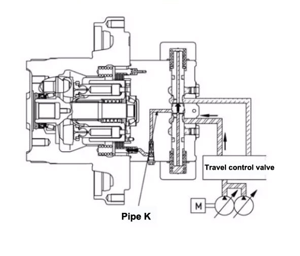
Reason for inspection: Dirty things block the small oil path (k) that releases the brake, causing the parking brake to not be released.
Failure analysis: (See the working process of the walking motor) When disassembling and assembling or the hydraulic oil is too dirty, dirty things enter the oil circuit, blocking the small oil circuit (k) that releases the brake. When walking, pressure oil cannot enter the oil circuit, it is impossible to release the brake by overcoming the thrust of the spring. As a result, the walking motor cannot rotate and cannot travel.
Troubleshooting: Clean the oil circuit, and pay attention to avoid the entry of dirt during the future disassembly and replacement of the hydraulic oil and filter element on time
