

Check and adjust pump PC control oil pressure
Pump PC control oil pressure check and adjustment tool
Measuring
After ensuring that the oil pressure of the working device, the slewing and walking oil circuits, and the basic pressure of the control oil circuit are normal, perform the measurement of the oil pressure in the pump PC control oil circuit. Lower the working device to the ground, and after shutting off the engine, release the remaining pressure in the pipeline by operating the control lever several times. Then slowly release the filler cap to relieve the pressure in the tank.
1. Measurement of PC valve output pressure (servo piston inlet pressure)
Together with pump output pressure, measure PC valve output pressure (servo piston inlet pressure) and compare the two results with each other.
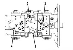
1) Open the pump room cover and remove the oil pressure measuring plugs (1), (2), (3) and (4).
• (1): Front pump discharge pressure detection screw plug
• (2): Rear pump discharge pressure detection screw plug
• (3): Front PC valve output pressure detection plug
• (4): Rear PC valve output pressure detection plug
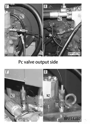
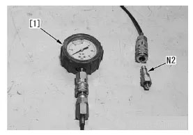
2) Install the connector N2 and connect it to the oil pressure gauge of the hydraulic tester N1.
Use 60MPa {600kg / cm2} oil pressure gauge
• This figure shows the measurement of pump discharge pressure.
3) Start the engine and keep it running until the temperature of the hydraulic oil rises to the working range.
4) After setting the following conditions, when the engine is running at high idle speed, measure the pump discharge pressure and PC valve output pressure (pressure at the servo piston inlet).
.
• Working mode: P-mode
• Rotary lock switch: ON
(2 level overflow turned on, resulting in high-pressure overflow)
• Work gear, slewing and walking: stick retraction overflow
Judging method:
If the following ratio is obtained between the pump discharge pressure and the PC valve output pressure (servo piston output pressure)
Rate, the PC valve is normal.
Measured oil pressure-oil pressure ratio
Pump discharge pressure-1
PC valve output pressure about × 0.6 (about × 3/5)
If there is an abnormality in the PC valve or servo piston, the output pressure of the PC valve (servo piston output pressure) becomes the same as the pump discharge pressure or close to O pressure.
5) After the measurement, remove the measuring tool and ensure that the machine returns to normal.
2. Measurement of PC-EPC valve output pressure
1) Open the pump chamber cover and remove the PC-EPC valve output pressure measurement
Measure the screw plug (5).
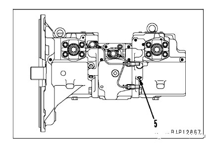
2) Install the connector N2 and connect it to the oil pressure gauge [1] of the hydraulic tester N1.
Use 6.0MPa {60kg / cm2} oil pressure gauge
3)
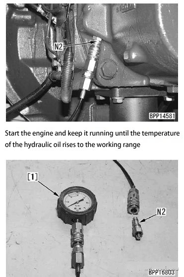
4) Measure hydraulic oil pressure when all levers are in the "neutral" position and the engine is running at high and low idle speeds.
When you see the following changes, you can assume that the PC-EPC valve output pressure is normal.
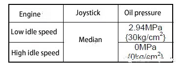
5) After the measurement, remove the measuring tool and ensure that the machine returns to normal.
Adjust teaching
If any of the following conditions occur and the PC valve appears to be damaged, adjust the PC valves (6) and (7) as follows.
• As the workload increases, the engine speed drops significantly.
• Engine speed is normal but working gear speed is low.
• (6): Front pump PC valve
• (7): PC valve for rear pump
The opposite width of the PC valve lock nut is 13mm, and the opposite width (within the width) of the adjusting screw is 4mm. Do not turn any other lock nuts or adjustment screws as they will affect the performance of the hydraulic pump.
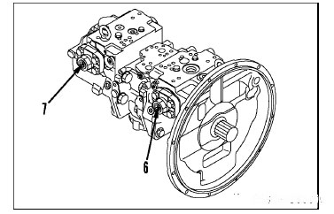
1. Loosen the locknut (8).
Before loosening the lock nut, mark the end of the adjustment screw so that you can know the position of the lock nut before adjustment (and the lock nut can be restored to its original position after reverse rotation).
2. Turn the adjusting screw (9) clockwise or counterclockwise to adjust.
Adjustment screw:
• When the working device speed is low, turn clockwise (to increase large pump absorbs torque).
• When the engine speed drops, turn counterclockwise (to reduce pump absorption torque).
The adjustment range of the adjustment screw is indicated below.
• Counterclockwise: within 1 turn
• Clockwise: within 1 turn
3. Tighten the locknut (8). Locknut: 27.5-34.3Nm {2.8-3.5kgm}
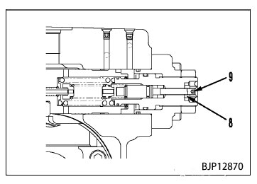
4. After adjustment, use the measurement procedure described above to ensure that the PC valve output pressure (servo piston inlet pressure) is normal.